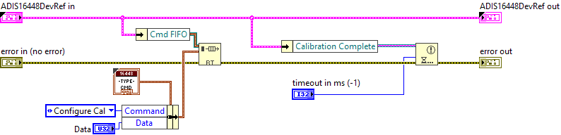
This VI triggers a re-calibration routine on the ADIS16470. This call will take approx. 100ms to run. The sensor <b><u>MUST</b></u> be completely still before calling this method. To set the amount of time before this call to calibrate call <b>ADIS16470 Set Re-calibration Time</b>. The default is ~1s.
A good use for this is to set the calibration time so a reasonable amount of time that the robot may be still (for example, while the robot is on the field before Autonomous). Then call this routine at the start of autonomous to set good calibration. The sensor uses the samples before this method is called in its calibration. The longer the time the better the result, though the improvement is lower after 8s-16s.
|
|
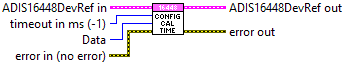
timeout in ms (-1) |
|
|
error in (no error) error in can accept error information wired from VIs previously called. Use this information to decide if any functionality should be bypassed in the event of errors from other VIs. Right-click the error in control on the front panel and select Explain Error or Explain Warning from the shortcut menu for more information about the error. |
|
|
status status is TRUE (X) if an error occurred or FALSE (checkmark) to indicate a warning or that no error occurred. Right-click the error in control on the front panel and select Explain Error or Explain Warning from the shortcut menu for more information about the error. |
|
|
code code is the error or warning code. Right-click the error in control on the front panel and select Explain Error or Explain Warning from the shortcut menu for more information about the error. |
|
|
source source describes the origin of the error or warning. Right-click the error in control on the front panel and select Explain Error or Explain Warning from the shortcut menu for more information about the error. |
|
|
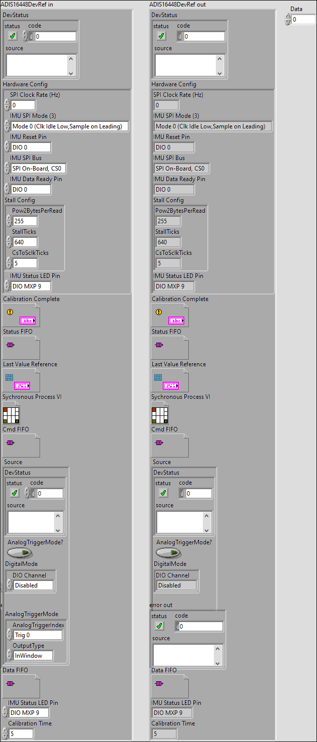
ADIS16448DevRef in |
|
|
DevStatus error in can accept error information wired from VIs previously called. Use this information to decide if any functionality should be bypassed in the event of errors from other VIs. Right-click the error in control on the front panel and select Explain Error or Explain Warning from the shortcut menu for more information about the error. |
|
|
status status is TRUE (X) if an error occurred or FALSE (checkmark) to indicate a warning or that no error occurred. Right-click the error in control on the front panel and select Explain Error or Explain Warning from the shortcut menu for more information about the error. |
|
|
code code is the error or warning code. Right-click the error in control on the front panel and select Explain Error or Explain Warning from the shortcut menu for more information about the error. |
|
|
source source describes the origin of the error or warning. Right-click the error in control on the front panel and select Explain Error or Explain Warning from the shortcut menu for more information about the error. |
|
|
Hardware Config |
|
|
SPI Clock Rate (Hz) |
|
|
IMU SPI Mode (3) |
|
|
IMU Reset Pin |
|
|
IMU SPI Bus |
|
|
IMU Data Ready Pin |
|
|
Stall Config |
|
|
Pow2BytesPerRead |
|
|
StallTicks |
|
|
CsToSclkTicks |
|
|
IMU Status LED Pin |
|
|
Calibration Complete |
|
|
Status FIFO |
|
|
Last Value Reference |
|
|
Sychronous Process VI |
|
|
Cmd FIFO |
|
|
Source Source specifies the source signal for the interrupt. |
|
|
DevStatus DevStatus describes the error status before this VI or function runs. The default is no error. |
|
|
status status is TRUE (X) if an error occurred before this node ran or FALSE (checkmark) to indicate a warning or that no error occurred before this node ran. The default is FALSE. |
|
|
code code is the error or warning code. The default is 0. If status is TRUE, code is an error code. If status is FALSE, code is 0 or a warning code. |
|
|
source source specifies the origin of the error or warning and is, in most cases, the name of the node that produced the error or warning. The default is an empty string. |
|
|
AnalogTriggerMode? AnalogTriggerMode? specifies, when TRUE, to use an analog trigger output instead of a digital input as the digital source. |
|
|
DigitalMode DigitalMode specifies information about the digital input you want to use as the digital source. |
|
|
DIO Channel DIO Module specifies the slot number on the CompactRIO device of the digital module you want to use. DIO Module can specify a value of Slot 4 or Slot 6. If DIO Module specifies a value of Default, this VI uses the default digital module. The default digital module is the first digital module, or the module in slot 4. |
|
|
AnalogTriggerMode |
|
|
AnalogTriggerIndex This list the number of available analog trigger logic implemented inside the FPGA code. As of rev 1.8 there is 8 available analog trigger logic. |
|
|
OutputType |
|
|
Data FIFO Source specifies the source signal for the interrupt. |
|
|
IMU Status LED Pin |
|
|
Calibration Time |
|
|
Data |
|
|
ADIS16448DevRef out |
|
|
DevStatus error in can accept error information wired from VIs previously called. Use this information to decide if any functionality should be bypassed in the event of errors from other VIs. Right-click the error in control on the front panel and select Explain Error or Explain Warning from the shortcut menu for more information about the error. |
|
|
status status is TRUE (X) if an error occurred or FALSE (checkmark) to indicate a warning or that no error occurred. Right-click the error in control on the front panel and select Explain Error or Explain Warning from the shortcut menu for more information about the error. |
|
|
code code is the error or warning code. Right-click the error in control on the front panel and select Explain Error or Explain Warning from the shortcut menu for more information about the error. |
|
|
source source describes the origin of the error or warning. Right-click the error in control on the front panel and select Explain Error or Explain Warning from the shortcut menu for more information about the error. |
|
|
Hardware Config |
|
|
SPI Clock Rate (Hz) |
|
|
IMU SPI Mode (3) |
|
|
IMU Reset Pin |
|
|
IMU SPI Bus |
|
|
IMU Data Ready Pin |
|
|
Stall Config |
|
|
Pow2BytesPerRead |
|
|
StallTicks |
|
|
CsToSclkTicks |
|
|
IMU Status LED Pin |
|
|
Calibration Complete |
|
|
Status FIFO |
|
|
Last Value Reference |
|
|
Sychronous Process VI |
|
|
Cmd FIFO |
|
|
Source Source specifies the source signal for the interrupt. |
|
|
DevStatus DevStatus describes the error status before this VI or function runs. The default is no error. |
|
|
status status is TRUE (X) if an error occurred before this node ran or FALSE (checkmark) to indicate a warning or that no error occurred before this node ran. The default is FALSE. |
|
|
code code is the error or warning code. The default is 0. If status is TRUE, code is an error code. If status is FALSE, code is 0 or a warning code. |
|
|
source source specifies the origin of the error or warning and is, in most cases, the name of the node that produced the error or warning. The default is an empty string. |
|
|
AnalogTriggerMode? AnalogTriggerMode? specifies, when TRUE, to use an analog trigger output instead of a digital input as the digital source. |
|
|
DigitalMode DigitalMode specifies information about the digital input you want to use as the digital source. |
|
|
DIO Channel DIO Module specifies the slot number on the CompactRIO device of the digital module you want to use. DIO Module can specify a value of Slot 4 or Slot 6. If DIO Module specifies a value of Default, this VI uses the default digital module. The default digital module is the first digital module, or the module in slot 4. |
|
|
AnalogTriggerMode |
|
|
AnalogTriggerIndex This list the number of available analog trigger logic implemented inside the FPGA code. As of rev 1.8 there is 8 available analog trigger logic. |
|
|
OutputType |
|
|
Data FIFO Source specifies the source signal for the interrupt. |
|
|
IMU Status LED Pin |
|
|
Calibration Time |
|
|
error out error in can accept error information wired from VIs previously called. Use this information to decide if any functionality should be bypassed in the event of errors from other VIs. Right-click the error in control on the front panel and select Explain Error or Explain Warning from the shortcut menu for more information about the error. |
|
|
status status is TRUE (X) if an error occurred or FALSE (checkmark) to indicate a warning or that no error occurred. Right-click the error in control on the front panel and select Explain Error or Explain Warning from the shortcut menu for more information about the error. |
|
|
code code is the error or warning code. Right-click the error in control on the front panel and select Explain Error or Explain Warning from the shortcut menu for more information about the error. |
|
|
source source describes the origin of the error or warning. Right-click the error in control on the front panel and select Explain Error or Explain Warning from the shortcut menu for more information about the error. |
"ADIS16448 Config Cal Time.vi History"
Current Revision: 32